
The type 1675, 1677 and 1678 voice cards, also known as the "Mark II", were designed to be even more flexible than the 1554 voice card. It can use one or two EPROMs, either 4K byte 2732s, or 8K byte 2764s. These can be configured several ways, as shown in Table 1.
| EPROM U8 | EPROM U9 | Function |
| 2732 | - | One 4K sound (same as 1554 kick, snare, etc.) |
| 2732 | - | Two 2K sounds (same as 1554 percussion) |
| 2764 | - | One 8K sound |
| 2764 | - | Two 4K sounds |
| 2732 | 2732 | One 8K sound |
| 2732 | 2732 | Two 4K sounds |
| 2764 | 2764 | One 16K sound |
| 2764 | 2764 | Two 8K sounds |
Table 1
The 1675 voice card uses a low pass CEM3320 voltage controlled filter (VCF) to smooth the digital output. (This is the same filter chip used in the Oberheim OB-Xa and OB-8 synthesizers). A few 1678A voice cards were manufactured, using a slightly different CEM3350 filter instead of the CEM3320. Otherwise, the 1678A is pretty much identical to the 1675C, and this document should apply to either, as far as configuration goes.
The following voices are all assembled on the same type of printed circuit board, with variations in components and jumper positions used to set individual characteristics.
The 1675 voice cards use one or two 2732 or 2764 EPROMs in various combinations. The EPROM sockets are pin compatible with 27128, 27256 and 27512 EPROMs, but only the top 4K or 8k bytes will be used - The 1675C card has EPROM address lines A15, A14 and A13 hardwired to a logic high state.
Every voice card has three possible triggers: 1, 2 and 3. These correspond to the three pushbuttons for a voice on the DMX front panel, from top to bottom, in that order. When a voice card is triggered, a binary counter starts addressing the EPROM(s) on the voice card, and the data bits feed into a Digital to Analog Converter (DAC). This multiplying DAC also behaves as a Voltage Controlled Amplifier (VCA), and its output goes through a low-pass Voltage controlled filter (VCF) before leaving the voice card. Two simple envelope generators are also included which can control the VCA and/or the VCF.
The sample rate on most voice cards is approximately 24000 samples per second, adjustable using the trimmer T1, and also depending on the value of capacitor C1.
There are several jumper settings that may be made to the generic voice card to change its playback configuration. In addition, there are some resistor and capacitor changes that will affect the sound.
With the exception of the A jumper block, the jumpers are numbered starting from 1 closest to the letter printed on the silk screen. The A jumper is the reverse of this, with pin 4 closest to the "A".
|
|
|
The A jumper, capacitor C4, diode D5, and resistors R7, R8 and R9 control the VCA decay envelope. See Table 2 for jumper and resistor combinations. When the decay envelope is enabled, the sound starts out playing back at full volume and gradually becomes quieter throughout the sample playback. The decay time is set by the value of C4, typically 2.2uF to 6.8uF. If C4 is not installed, the decay time is nearly instantaneous.
The A jumper also controls the behavior of the VCF envelope decay. Pin 1 is common, and should connect one of the other three pins.
| Jumper A | C4 | D5 | R7 | R8 | R9 | Trigger 1 VCA | Trigger 2 VCA | Trigger 3 VCA |
| X | Out | X | X | 4.7K | Out | - | - | - |
| Connect 1 to 3 | Installed | 1N4148 | 4.7K | Out | 4.7K | decay enabled | - | - |
| Connect 1 to 4 | Installed | 1N4148 | 4.7K | Out | 4.7K | decay enabled | decay enabled | - |
| Connect 1 to 4 | Installed | 1N4148 | 4.7K | Out | Out | decay enabled | decay enabled | decay enabled |
For minimal low pass filtering, a simple approach is to just put a jumper wire across capacitor C3 pads. This will set the filter in a wide open configuration, independent of any other settings described below.
There are several settings that affect the VCF mode of operation. Jumper A, capacitor C3 and resistors R12 and R13 control the filter frequency as shown in Table 3. The decay time is controlled by the value of C3, typically around 10uF.
| Jumper A | C3 | R12 | R13 | Trigger 1 VCF | Trigger 2 VCF | Trigger 3 VCF |
| Connect 1 to 2 | Out | 4.7K | Out | Wide open | Wide open | Wide open |
| Connect 1 to 3 | Installed | Out | 10K | Decay envelope | Wide open | Wide open |
| Connect 1 to 4 | Out | 4.7K | Out | Track sample rate | Track sample rate | Track sample rate |
| Connect 1 to 4 | Installed | 4.7K | Out | Decay/track combo | Decay/track combo | Decay/track combo |
| Connect 1 to 4 | Installed | Out | 10K | Decay envelope | Decay envelope | Decay envelope |
The arrangement of diodes D1, D2, D3 and D4, and resistors R4 and R5 determine the control of the triggers on sound pitch or amplitude. See Table 4 for the allowable configurations. The amount of any changes are controlled by the setting the values of R4 (trigger 1) and R5 (triggers 1 and 2).
| D1 | D2 | D3 | D4 | R4 | R5 | Trigger 1 | Trigger 2 | Trigger 3 |
| 1N4148 | Out | 1N4148 | Out | Installed | Installed | Raises pitch (R4 & R5) | Raises pitch (R4) | - |
| 1N4148 | Out | Out | 1N4148 | Installed | Installed | Raises pitch (R4) and lowers volume (R5) | Raises pitch (R4) | - |
| Out | 1N4148 | 1N4148 | Out | Installed | Installed | Lowers volume (R4) and raises pitch (R5) | Lowers volume (R4) | - |
| Out | 1N4148 | Out | 1N4148 | Installed | Installed | Lowers volume (R4 & R5) | Lowers volume (R4) | - |
| X | X | 1N4148 | Out | Out | Installed | Raises pitch (R5) | Raises pitch (R5) | - |
| X | X | Out | 1N4148 | Out | Installed | Lowers volume (R5) | Lowers volume (R5) | - |
| 1N4148 | Out | X | X | Installed | Out | Raises pitch (R4) | - | - |
| Out | 1N4148 | X | X | Installed | Out | Lowers volume (R4) | - | - |
| X | X | X | X | Out | Out | - | - | - |
Jumper wire G controls the path of the external control voltage to control either playback pitch (connect pins 2 and 3) or volume (connect pins 2 and 1). The external control voltage comes into the DMX through the Molex jack on the back of the unit.
Resistor R11 sets the default loudness of the sound.
Capacitor C1 may be used to set the nominal sample rate. Typical values range from 0.0022uF to 0.0047uF.
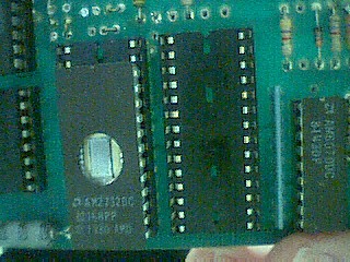
U8 should be a 2764, containing two 4K samples. U9 should be a 2732, containing one 4K sample.
The sound for the top trigger button on on the 2764 at addresses 1000h - 1FFFFh, the
sound for the middle trigger button go on the 2764 at addresses 0000h - 0FFFh. The sound
for the lower trigger button goes on the 2732.
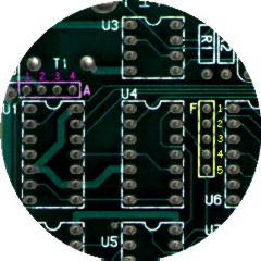
Jumpers A, D: connect A1 to A4. Connect a wire from jumper position A2 (on the back of the board) to jumper position D2. No other connections to the D jumper group.
Jumper F: Connect F3 to F4.
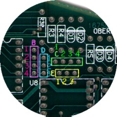
Jumpers B, C: Remove any existing jumpers from the B and C groups. Connect a wire from jumper B1 to jumper C4. Connect a wire from jumper C3 to jumper B3.
Jumper E: Connect E2 to E3.
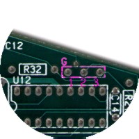
Jumper G: Connect G2 to G3
Jumper across C3.
Cut out or otherwise remove the following parts: C3, C4, R4, D1, D2, R5, D3, D4, R9, R12, R13.
If you want to vary the sample rates between the three sounds, re-install D1 and D3, and experiment with different resistor
values for R4 and R5.
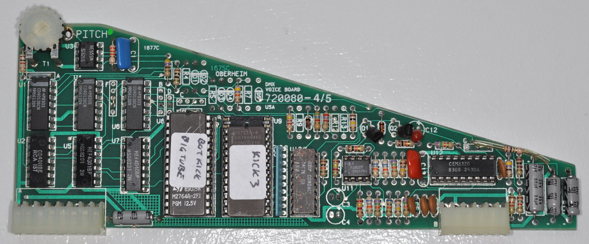
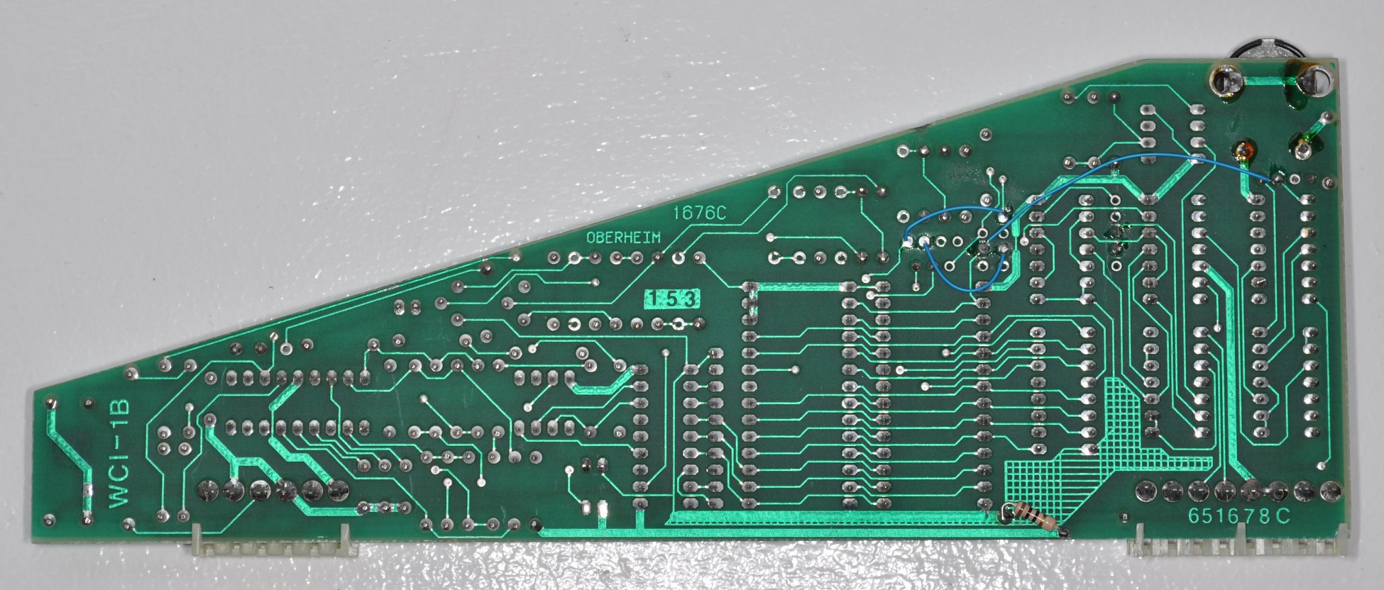
Click the thumbnail images to see photos of a triple voice card
modification:
This page maintained by Paul J. White.