This document is intended to provide guidance for those wishing to modify Oberheim DMX voice cards. A general knowledge of electronics and soldering is assumed. If the reader is not comfortable making any of these changes personally, a competent electronic technician should be consulted.
The following voices are all assembled on the same type of printed circuit board, with variations in components and jumper positions used to set individual characteristics. Two versions of the circuit board exist, numbered on the component side of the board (near the EPROM) as either 1554A or 1554B. The 1554B is characterized by having a larger diameter wheel on the pitch control trimmer. The other differences are minor, and are mentioned below.

The 1554A and 1554B voice cards use a single 2732 EPROM. One or two sounds may be programmed on the EPROM.
Every voice card has three possible triggers: 1, 2 and 3. These correspond to the three pushbuttons for a voice on the DMX front panel, from top to bottom, in that order. When a voice card is triggered, a binary counter starts addressing the EPROM(s) on the voice card, and the data bits feed into a Digital to Analog Converter (DAC). This multiplying DAC also behaves as a Voltage Controlled Amplifier (VCA), and its output goes through a low-pass filter before leaving the voice card. A simple envelope generator is also included which can control the VCA.
The sample rate on most voice cards is approximately 24000 samples per second, adjustable using the trimmer T1, and also depending on the value of capacitor C2. A 2732 EPROM stores 4096 samples, giving a typical total playback time of about 0.171 seconds (171 milliseconds).
There are several jumper settings that may be made to the generic voice card to change its playback configuration. In addition, there are some resistor and capacitor changes that will affect the sound.
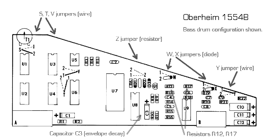
The S and Z jumpers control the VCA decay envelope. The S jumper is a wire and the Z jumper is a 4.7K resistor. (On the 1554A voice card, jumper S is permanently wired to position 1, and the Z jumper is arranged differently than shown in the drawing). See the Table 1 for jumper S and Z combinations. When the decay envelope is enabled, the sound starts out playing back at full volume and gradually becomes quieter throughout the sample playback. The decay time is set by the value of C3, typically 2.2uF to 6.8uF. If C3 is not installed, the decay time is nearly instantaneous. The decay envelope effect is used on the standard Bass, Hi-Hat, Tom 1 and Tom 2 cards.
| Jumper S | Jumper Z | Trigger 1 Envelope | Trigger 2 Envelope | Trigger 3 Envelope |
| 1 | 1 | - | - | - |
| 1 | 2 | decay enabled | - | - |
| 1 | Open | decay enabled | - | - |
| 2 | 1 | - | - | - |
| 2 | 2 | decay enabled | decay enabled | - |
| 2 | Open | decay enabled | decay enabled | decay enabled |
The T and V jumper wires select the length of the sample. Both jumpers should always be set to the same position. With both jumpers in position 1, the entire 2732 EPROM is played back for all triggers (4096 bytes). When both jumpers are in position 2, the sample length is half of the EPROM size (2048 bytes). In this case trigger 3 plays the first half of the EPROM (addresses 0 - 2047), and triggers 1 and 2 play the second half of the EPROM (addresses 2048 - 4095).
Jumper W (a 1N4148 diode, rather than a wire) selects pitch or amplitude control for trigger 1 and 2 sounds. With W in position 1, triggers 1 and 2 will raise the pitch (sample rate) of the sound. In position 2, triggers 1 and 2 will decrease the amplitude of the sound. In either case, the pitch or amplitude is changed by an amount determined by the value of resistor R12. If R12 is removed altogether, triggers 1 and 2 will have no affect on pitch or amplitude.
Jumper diode X (1N4148) and resistor R17 control the pitch or amplitude of the sound in combination with jumper W and resistor R12 settings, but for trigger 1 sounds only.
Jumper wire Y controls the path of the external control voltage to control either playback pitch (position 1) or volume (position 2). The external control voltage comes into the DMX through the Molex jack on the back of the unit.
Resistor R8 sets the general loudness of the sound when not otherwise controlled by jumper W and jumper X combinations.
Resistors R13, R14, R15, R18, R19 and R20 set the cutoff frequency of the lowpass filter. For typical values, see the various standard voice card settings.
Capacitor C2 may be used to set the nominal sample rate. Typical values range from 0.0022uF to 0.0047uF.
This page maintained by Paul J. White.