Oberheim DMX MIDI Upgrade Installation
The Electrongate MIDI Upgrade Kit for the Oberheim DMX drum machine adds MIDI capability and 7000 note capacity
to the DMX. The kit version can be installed by anyone posessing moderate experience in electronic assembly
and soldering. If you don't feel up to the task, you can have the MIDI kit installed professionally by
Electrongate for an additional $50.
But if you're ready to give it a try, these instructions will take you through the process, step by step.
Parts supplied with Electrongate MIDI Kit:
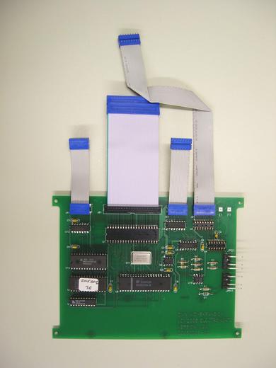
- (1) Assembled and tested MIDI circuit board.
- (4) #6 threaded standoffs.
- (1) MIDI cable assembly with mounting plate and modified right-side walnut end panel.
- (1) Addendum to owner's manual.
- (1) Installation instructions.
Tools required for installation:
- #2 Phillips screwdriver
- 1/4 inch nut driver
- Small flat-blade screwdriver or DIP IC chip puller
- Small diagonal cutters
- X-acto knife with #11 blade
- Soldering iron and rosin-core tin/lead solder
Installation: Step By Step
- Turn off the power and disconnect the AC power cable from the DMX.
- Remove the two screws on the front of the DMX and open the cover.
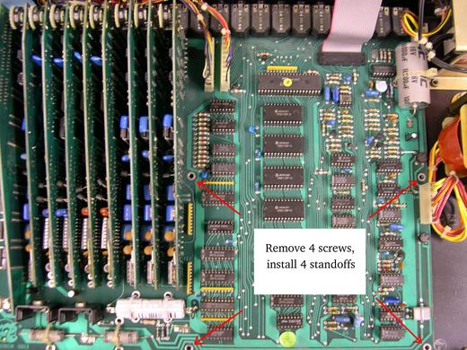
- Remove four screws from the DMX main board as shown below and set them aside. These will
be reused later.
- Install the four standoffs provided in place of the screws that were just removed.
(If your DMX is already equipped with a memory expansion board, remove it. The MIDI upgrade will take its place).
- Remove IC 12 (Z-80 CPU) from the DMX main board and install it in socket U1
on the MIDI board. (Your MIDI board may already have a Z-80
installed. If so, just set the old Z-80 aside).
Notes:
- Observe IC polarity -- line up notch in IC with notch in socket.
- IC numbers are printed on the circuit board near each IC.
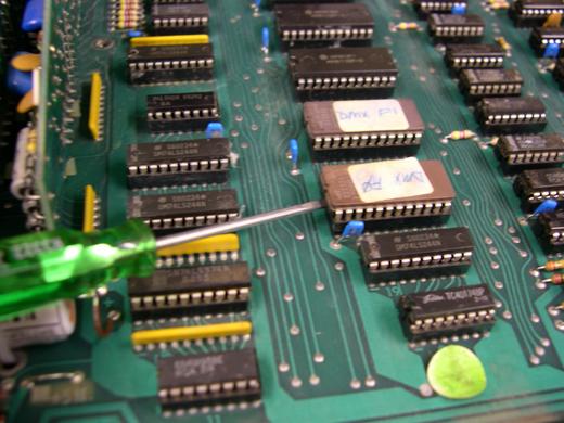
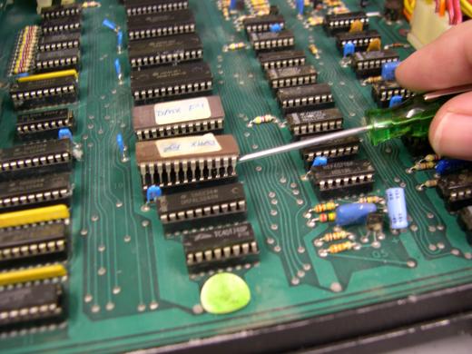
- Use a small flat blade
screwdriver to remove ICs by alternately levering each end up a little at a time. Keep the screwdriver between
the IC and the socket; not under the socket.
- Be careful not to bend the pins. If you do bend any pins,
straighten them out before reinstalling the IC.
|
|
- Remove IC 20 (74C174 or 40174) from the DMX main board and install it in socket
U3 on the MIDI board.
- Remove IC 23 (4013) from the DMX main board and install it in socket U4
on the MIDI board.
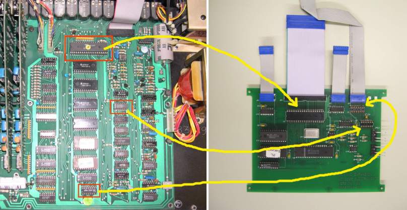
- Remove four RAM ICs and two EPROMs (IC 13, 14, 15, 16 17 and 18) from the DMX main board.
Remove IC 2 (74LS42) and IC 3 (4071). These eight parts become surplus and
may be discarded.
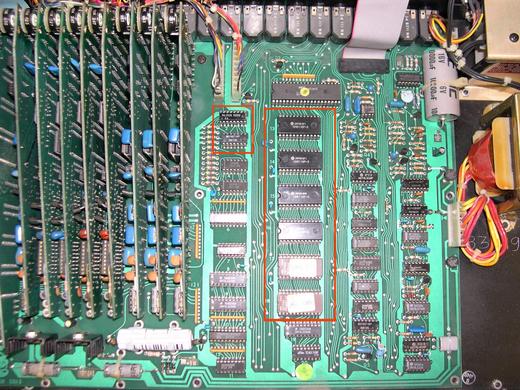
After all the indicated ICs have been removed, the DMX main board should look like this:
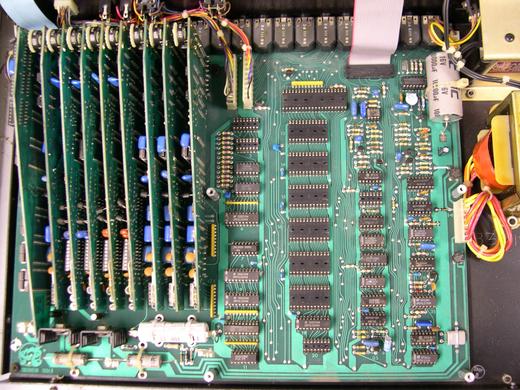
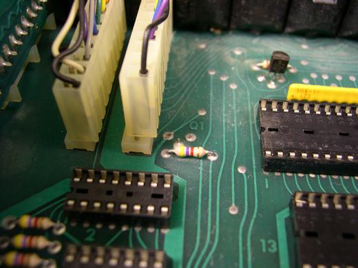
- Locate transistor Q1 (left of IC 12) and using diagonal cutters,
snip three leads and discard the transistor.
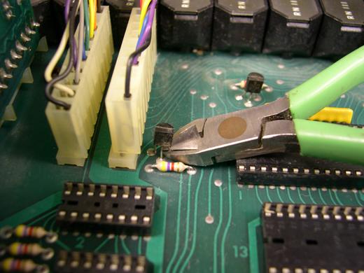
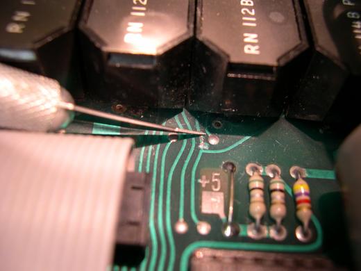
- Here's the tricky part: Using a sharp X-acto knife, cut the indicated circuit board trace as shown below and scrape the solder mask from the circuit
trace just behind the cut. (It may help to temporarily unplug ribbon cable G and pull it back to gain
access to this area).
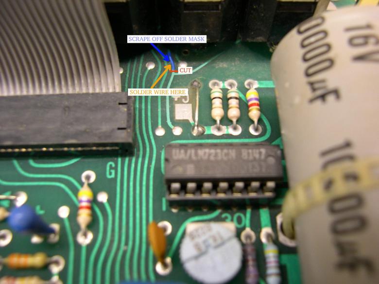
Preparing to make the cut:
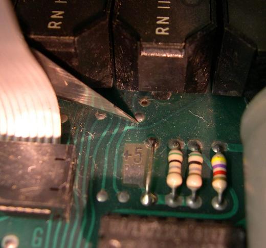
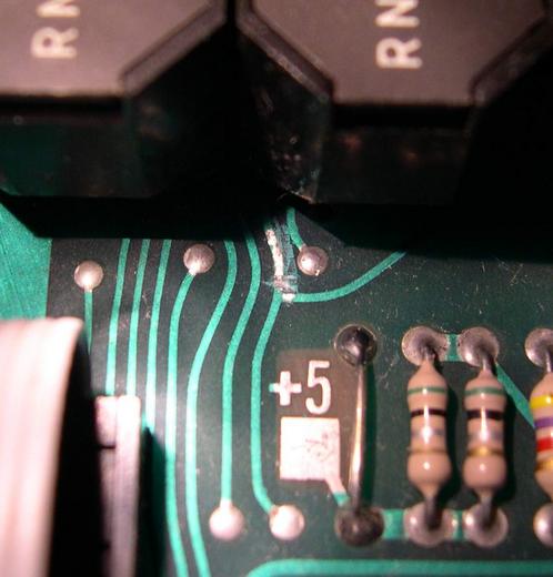
The cut should look like this when finished. It's best to use two cuts about a millimeter apart to make
a "V" shaped pass through the trace into the fibreglas board below. Remove the debris from the board.
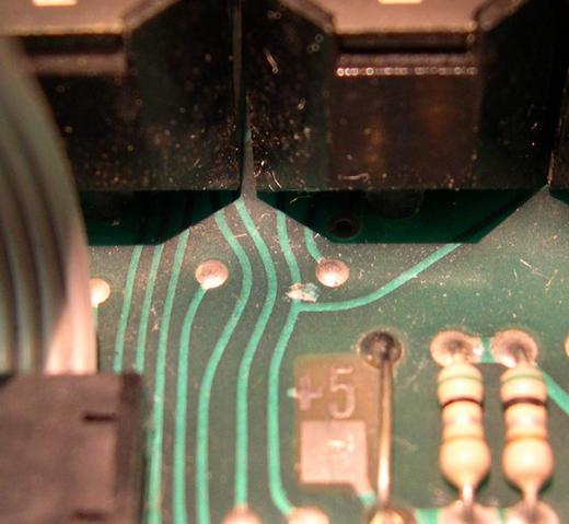
Use the edge of the knife to scrape the green coating (solder mask) covering the copper trace as shown. When the
shiny tinned surface is visible through the entire width of the trace, you have scraped enough.
It should look like this when the solder mask is removed:
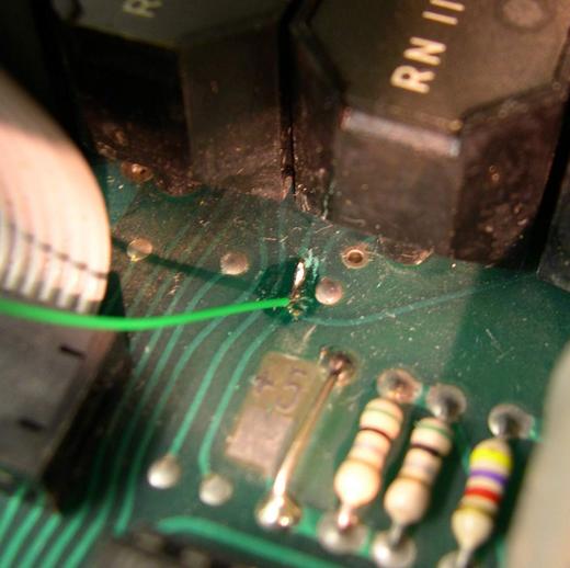
- Tin the bare copper where the solder mask was removed, and solder wire F from the MIDI
board to this point.
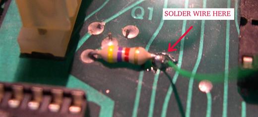
- Solder wire E to the right side of the resistor next to Q1, which was just removed.
- Plug the ribbon cables from the MIDI board into the DMX main board.
| Cable | plugs into |
|---|
| JA1 | IC socket 3 |
| JB1 | IC socket 12 |
| JC1 | IC socket 23 |
| JD1 | IC socket 20 |
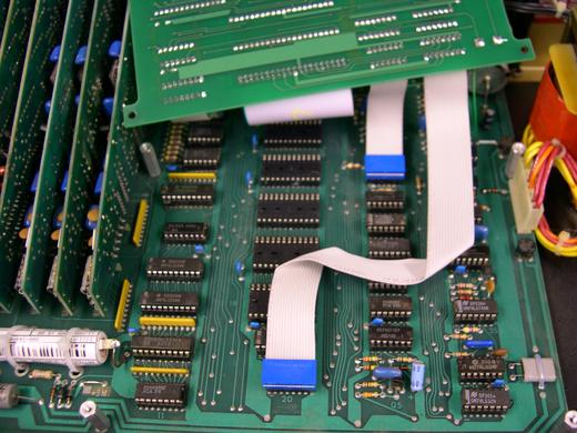
Notice that JC1 and JD1 flip under the MIDI board in order to reach their sockets. Fold cable JD1 as shown.
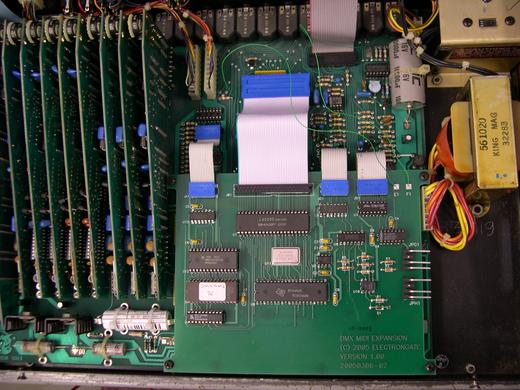
- Using the screws removed in step 3, attach the MIDI board to the standoffs.
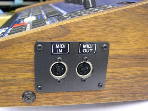
- Remove the right side wooden end panel by undoing two screws on the outside, and replace it with the
new end panel which has two MIDI jacks installed. The old wooden panel may be sent back to Electrongate for
a $20 credit.
- If you want to make your own modifications to the end panel, use this cutting
diagram. A plunge router with a 1/4 in diameter bit works well for the cutout if you make two or three passes, cutting a
little bit deeper with each pass. Use the jack plate itself as a drilling guide for the mounting screws. Predrill the screw
holes with a 5/64 inch drill bit (test on a piece of scrapwood to make sure this hole size will work with the screws
provided).
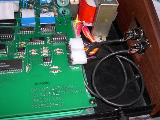
- Plug the cable from the MIDI IN jack into connector JPH1 on the MIDI board, and plug the MIDI OUT cable
into connector JPG1.
- Double-check the installation and make sure all the ribbon cables are plugged in correctly.
Then close the front cover, plug in the power cable and turn on the DMX while holding the
ERASE button (this will initialize the new memory).
Troubleshooting
In case there is a problem with the installation, check for the following common problems.
| Symptom | Possible problems/solutions |
|---|
| No display |
- Plug in power cable and turn on power switch.
- Make sure the front panel ribbon cables are plugged in properly.
- Make sure the MIDI board ribbon cables are plugged in correctly to the right sockets on the DMX main board.
- Check the orientation of all ICs that were moved from the DMX main board to the MIDI board. Check for bent pins.
- Make sure that the EPROMs were removed from the DMX main board.
|
| DMX works intermittently |
- Make sure that all the old RAM ICs were removed from the DMX main board.
- Make sure all cables are plugged in securely.
|
| No DMX clock or no clock out |
- Check installation of MIDI board wires E and F.
|
| MIDI not working |
- Check for swapped MIDI input/output cables.
|
| Errors in data / sequences lost after power off |
- Battery may be dead. Old batteries lose their ability to hold a charge after several years.
Check voltage between ground and the +5M test point with power turned off. Should be 3 volts or higher.
- Hold ERASE button down while turning power on to reinitialize memory.
|
For further assistance, contact Electrongate by email.


